Supplemental Data
Contains additional simulation data for the development of control algorithms for the Spot robot and simulations.
Contents
Table for the variable max knee torque due to the knee linkage.
Joint Order
All repeated fields for commands and state are in a consistent order as outlined in spot_constants.proto.
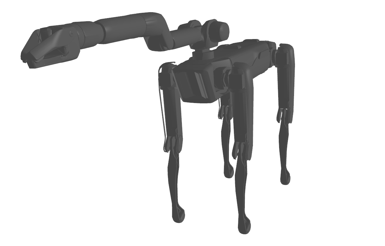
Robot Morphology
Robot structure can be found by inspecting the full URDF located here. Note: This URDF contains additional information compared to what is available through the RobotStateService and the URDF for an armless robot located here.
Joint Transmission Details
Joint Gear Ratios and Max Motor Torque
Most joints are simply actuated with a constant gear ratio.
| Joint | Gear Ratio | Max motor torque |
|---|---|---|
| HX | 51 | 0.88 |
| HY | 51 | 0.88 |
| KN | variable | 1.50 |
| SH0 | 101 | 0.89 |
| SH1 | coupled | 0.89 |
| EL0 | coupled | 0.89 |
| EL1 | 101 | 0.23 |
| WR0 | 101 | 0.23 |
| WR1 | 101 | 0.23 |
| F1X | 56.55 | 0.20 |
Knee Joints
The Spot robot knee is actuated using a ball-screw and push-rod mechanism connected to the lower leg. Due to the push-rod’s geometry, the maximum torque achievable varies depending on the configuration. The knee exhibits its greatest strength at the midpoint of its range and its weakest when fully flexed or extended. For details on the variable transmission ratio, refer to the file available here. This transmission ratio describes the motor input to knee angle output relationship as:
Tr(q_kn) = qd_motor / qd_kn
Coupled SH1/EL0 Joints
The SH1/EL0 joints are driven by a coupled set of input actuators. The 2x2 Jacobian describing the output velocities is:
[qd_sh1; qd_el0] = (1/101) * [1 0; -1 1] * [qd_motor0; qd_motor1]