Electrical Interface
The Spot robot’s two payload ports provide power and communication to the robot through a DB25 connection. The robot presents a socket DB25 connector at each payload port, pictured below. Note that pin 1 is on the right looking down at the robot. The payload must include a mating DB25 male connection in the proper orientation.
Robot presents DB25 socket
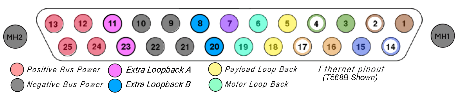
Payload port pinouts by category
| Category | Pins | Specifications |
|---|---|---|
| Power | 12, 13, 24, 25 | Voltage supply range: 35-59V Absolute Maximum Voltage: 72V Max current: 3A/pin Max power: 150W/port Bulk capacitance: 150uF/port |
| Communication | 1-4, 7, 14-17 | Ethernet: 1000Base-T PPS Accuracy: 5ppm PPS Frequency: 1Hz |
| Safety Loops | 5 to 18, 6 to 19, 8 to 20, 11 to 23 | Payload power interlock Motor power interlock Extra interlock loop (do not remove) Extra interlock loop (do not remove) |
Payload port PIN specifications
| Pin # | Name | Description |
|---|---|---|
| 1 | ETH0_D_N | Ethernet Pair D negative |
| 2 | ETH0_D_P | Ethernet Pair D Positive |
| 3 | ETH0_B_N | Ethernet Pair B negative |
| 4 | ETH0_B_P | Ethernet Pair B Positive |
| 5 | PL_SAFETY_O | Payload power enabled when continuity is established between this pin and pin 18 |
| 6 | MP_SAFETY_O | Robot motor power enabled when continuity is established between this pin and pin 19 |
| 7 | PPS | Pulse-Per-Second signal referenced to payload ground |
| 8 | EXTRA_SAFETY_A | Extra loop back. When designing a payload make sure to jumper to pin 20 |
| 9 | P_GND | Ground Reference for the payload. Each pin supports 3A of return current. |
| 10 | P_GND | Ground Reference for the payload. Each pin supports 3A of return current. |
| 11 | EXTRA_SAFETY_B | Extra loop back. When designing a payload make sure to jumper to pin 23 |
| 12 | PWR | Unregulated payload power from robot battery. Each pin supports 3A of supply current. |
| 13 | PWR | Unregulated payload power from robot battery. Each pin supports 3A of supply current. |
| 14 | ETH0_C_N | Ethernet Pair C negative |
| 15 | ETH0_C_P | Ethernet Pair C Positive |
| 16 | ETH0_A_N | Ethernet Pair A negative |
| 17 | ETH0_A_P | Ethernet Pair A Positive |
| 18 | PL_SAFETY_IN | Payload power enabled when continuity is established between this pin and pin 5 |
| 19 | MP_SAFETY_IN | Robot motor power enabled when continuity is established between this pin and pin 6 |
| 20 | EXTRA_SAFETY_A | Extra loop back. When designing a payload make sure to jumper to pin 8 |
| 21 | P_GND | Ground Reference for the payload. Each pin supports 3A of return current. |
| 22 | P_GND | Ground Reference for the payload. Each pin supports 3A of return current. |
| 23 | EXTRA_SAFETY_B | Extra loop back. When designing a payload make sure to jumper to pin 11 |
| 24 | PWR | Unregulated payload power from robot battery. Each pin supports 3A of supply current. |
| 25 | PWR | Unregulated payload power from robot battery. Each pin supports 3A of supply current. |
| MH1, MH2 | P_GND | Connector Shell and Mounting Hardware is connected to payload ground |
Payload power requirements
Payloads require a battery to be installed in the robot to operate. The robot is powered by a 600W-hr Lithium-ion battery pack that also provides power to payloads through a dedicated enable circuit. Battery voltage ranges from 35V for a fully discharged battery to 58.8V for a full charge.
Regenerative energy from the robot’s motors can cause the robot’s bus voltage to exceed the normal battery voltage range for short durations. The robot contains a clamping circuit to ensure the battery voltage bus never exceeds 72V.
Electrical components in payloads should be selected to handle a maximum payload input voltage of at least 80V.
Payload power is enabled when pins 5 (PL_SAFETY_O) and 18 (PL_SAFETY_IN) are shorted together on both payload ports. Both payload ports are powered from the same bus. Power is enabled through a soft-start circuit ensuring a monotonic voltage rise. The bus can support inrush current for up to 150uF of bulk capacitance in each payload, or 300uF total.
The robot includes a current limiting circuit that will disable power to the payload in the event of an unintended current spike. The average power for each payload connector must not exceed 150W. The resettable current limiting circuit in the robot will disable payload power if the total current for both payloads combined exceeds a limit ranging from 9-13A. If an overcurrent event occurs and payload power is disabled, the current limiting circuit can be reset by cycling robot power using the power button.
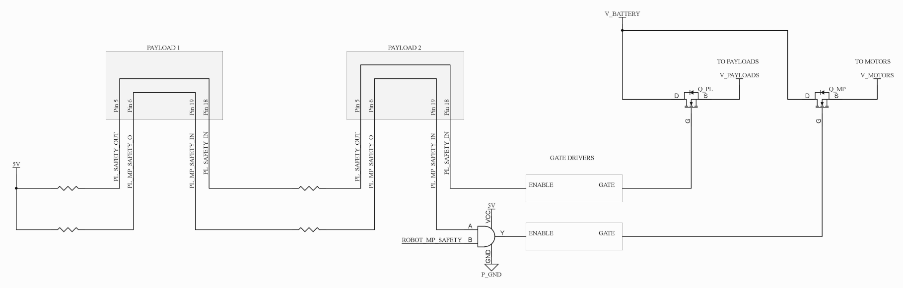
Motor power safety
The payload interface contains a safety interlock connection that allows the payload to disable motor power to all motors in the robot. All payloads must therefore ensure continuity between pins 6 (MP_SAFETY_O) and 19 (MP_SAFETY_IN); pins 5 (PL_SAFETY_IN) and 18 (PL_SAFETY_O); pins 8 (EXTRA_SAFETY_A) and 20 (EXTRA_SAFETY_A); as well as pins 11 (EXTRA_SAFETY_B) and 23 (EXTRA_SAFETY_B) at all times for the robot to operate. If electrical continuity between these pins is interrupted, the robot will immediately disable power specific systems. If the robot is standing, this will cause the robot to fall to the ground, or cause payloads to power off.
Payload port requirements
The robot’s payload caps include circuitry that completes the circuit between the pins involved in this system. If there is no payload present, the cap(s) must be installed to allow the robot to function. If the caps are removed or become loose during operation, the robot will immediately disable motor power and sit down.
Robot Communication and pulse-per-second (PPS)
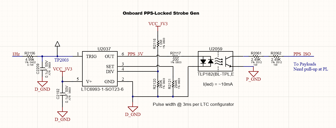
The payload connector includes pins to provide 1000Base-T Ethernet for connectivity to the payload. The robot also provides a Pulse Per Second (PPS) signal to the payloads via pin 7 (PPS) referenced to P_GND as shown below.
This signal operates at 1Hz with 5ppm accuracy. The payload can use this signal for synchronization with data provided by the robot. Spot’s CPU system times are synchronized to this pulse and can be communicated to the payload through the API.
Payloads must include a pull-up resistor to the appropriate logic voltage to accommodate the open collector output circuit as shown below, with a maximum current of 10mA. The pull-up resistor value must consider the series resistance on the robot (shown in the schematic below) to ensure adequate logic-low and logic-high signaling.